This note looks at the Open Compute Project distributed Uninterruptable Power Supply (UPS) and server Power Supply Unit (PSU). This is the last in a series of notes looking at the Open Compute Project. Previous articles include:
· Open Compute Mechanical Design
The open compute uses a semi-distributed uninterruptable power supply (UPS) system. Most data centers use central UPS systems where large the UPS is part of the central power distribution system. In this design, the UPS is in the 480 3 phase part of the central power distribution system prior to the step down to 208VAC. Typical capacities range from 750kVA to 1,000kVA. An alternative approach is a distributed UPS like that used by a previous generation Google server design.
In a distributed UPS, each server has its own 12VDC battery to serve as backup power. This design has the advantage of being very reliable with the batter directly connected to the server 12V rail. Another important advantage is the small fault containment zone (small “blast radius”) where a UPS failure will only impact a single server. With a central UPS, a failure could drop the load on 100 racks of servers or more. But, there are some downsides of distributed UPS. The first is that batteries are stored with the servers. Batteries take up considerable space, can emit corrosive gasses, don’t operate well at high temperature, and require chargers and battery monitoring circuits. As much as I like aspects of the distributed UPS design, it’s hard to cost effectively and, consequently, is very uncommon.
The Open Compute UPS design is a semi-distributed approach where each UPS is on the floor with servers but rather than having 1 UPS per server (distributed UPS) or 1 UPS per order 100 racks (central UPS with roughly 4,000 servers), they have 1 UPS per 6 racks (180 servers).
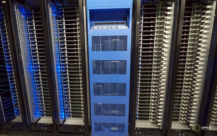
In this design the battery rack is the central rack flanked by two triple racks of servers. Like the server racks, the UPS is delivered 480VAC 3 phase directly. At the top of the battery rack, they have control circuitry, circuit breakers, and rectifiers to charge the battery banks.
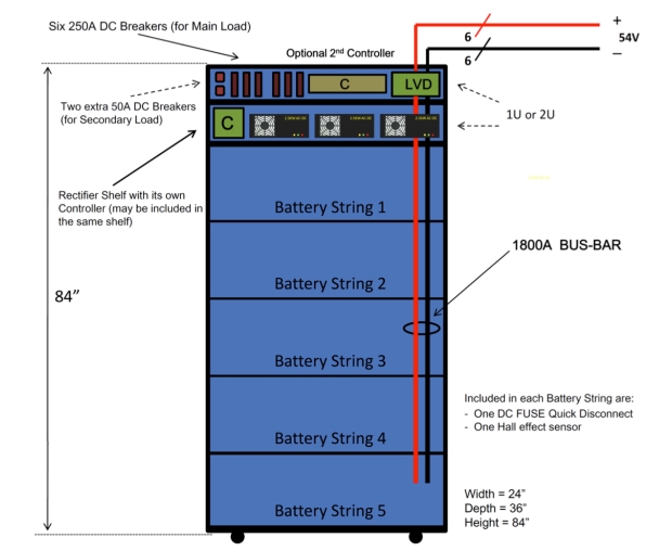
What’s somewhat unusual in the output stage of the UPS doesn’t include inverters to convert the direct current back to the alternating current required by a standard server PSU. Instead the UPS output is 48V direct current which is delivered directly to the three racks on either side of the UPS. This has the upside of avoiding the final invert stage which increases efficiency. There is a cost to avoiding converting back to AC. The most important downside is they need to effectively have two server power supplies where one accepts 277VAC and the other accepts 48VDC from the UPS. The second disadvantage is using 48V distribution is inefficient over longer distances due to conductor losses at high amperage.
The problem with power distribution efficiency is partially mitigated by keeping the UPS close to servers where the 6 racks its feeds are on either side of the UPS so the distances are actually quite short. And, since the UPS is only used during short periods of time between the start of a power failure and the generators taking over, the efficiency of distribution is actually not that important a factor. The second issue remains, each server power supply is effectively two independent PSUs.
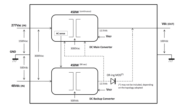
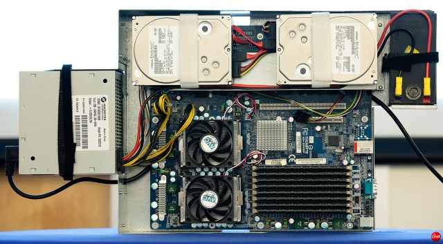
The server PSU looks fairly conventional in that it’s a single box. But, included in the single box, is two independent PSUs and some control circuitry. This has the downside of forcing the use of a custom, non-commodity power supply. Lower volume components tend to cost more. However, the power supply is a small part of the cost of a server so this additional cost won’t have a substantially negative impact. And, it’s a nice, reliable design with a small fault containment zone which I really like.
The Open Compute UPS and power distribution system avoids one level of power conversion common in most data centers, delivers somewhat higher voltages (277VAC rather than 208VAC) close to the load, and has the advantage of a small fault zone.
b: http://blog.mvdirona.com / http://perspectives.mvdirona.com
They effectively use two independent PSUs each of which feeds the same 12V DC rail. If one goes cold, the other picks up the load. This avoids the need for an ATS. Its essentially exactly the same design used by expensive multi-corded servers. Each power cord powers a PSU and both PSUs power the same 12v rail.
–jrh
james, i know what you mean, but the trasnfer scheme is the highlight of this solution, we have to use STS or ATS to switch traditionally, but in this design, how to transfer smoothly in 20 milisecond, how can they they make it.
The logic of using 48VDC on the backup system is that, in normal operation it is not used. As a consequence, the efficiency of the backup system isn’t a significant factor in overall facility efficiency.
as james have mentioned 48V is not as good, so we can improve the voltage to 270Vdc or even higher, by this we can put the ups and battery to battery room without the influence tempreture, and support more rack.
the critical point is the transfer from 277Vac to 48Vdc, how can wake up the 48V system and transfer smoothly in 2oms?