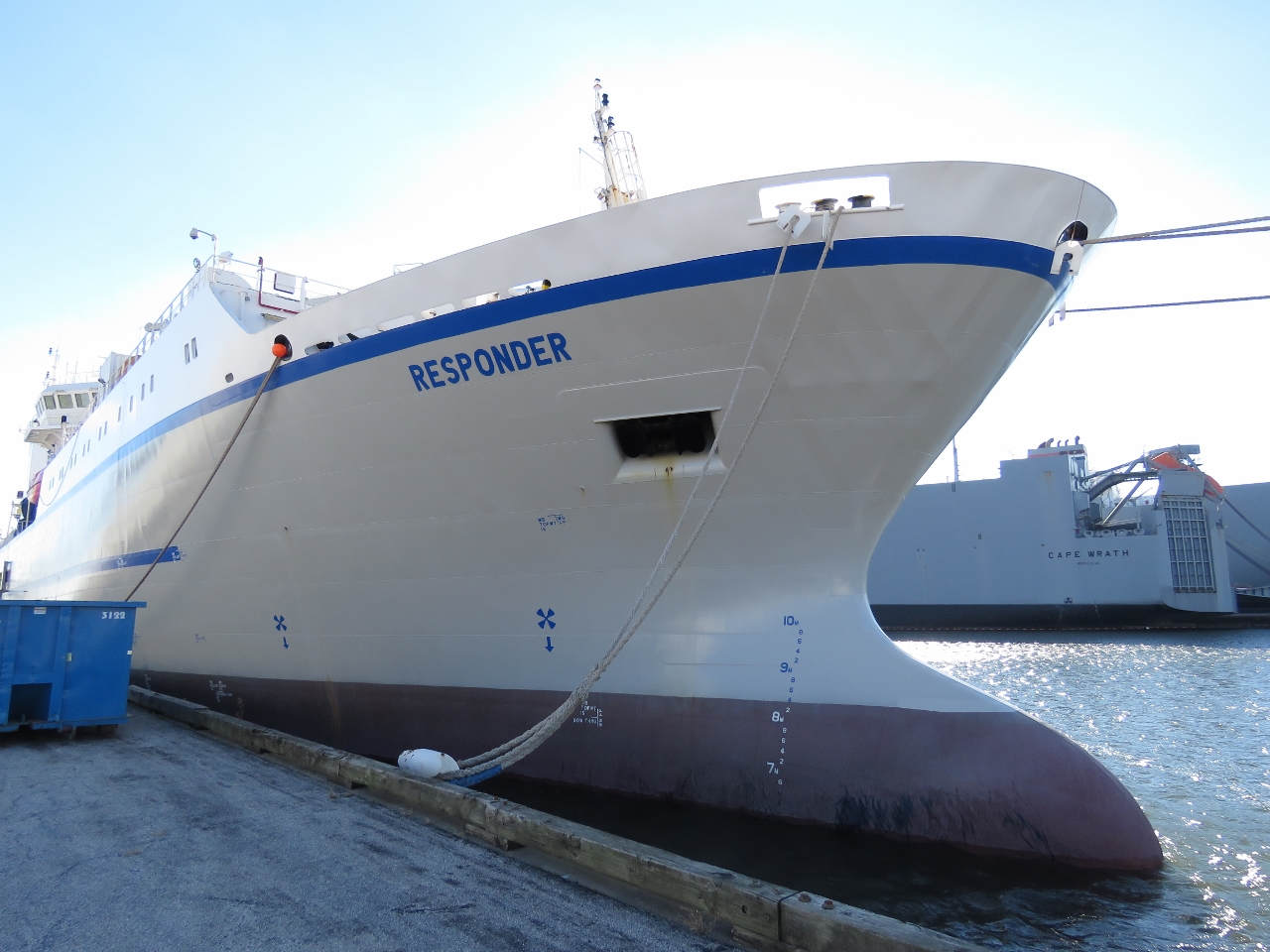
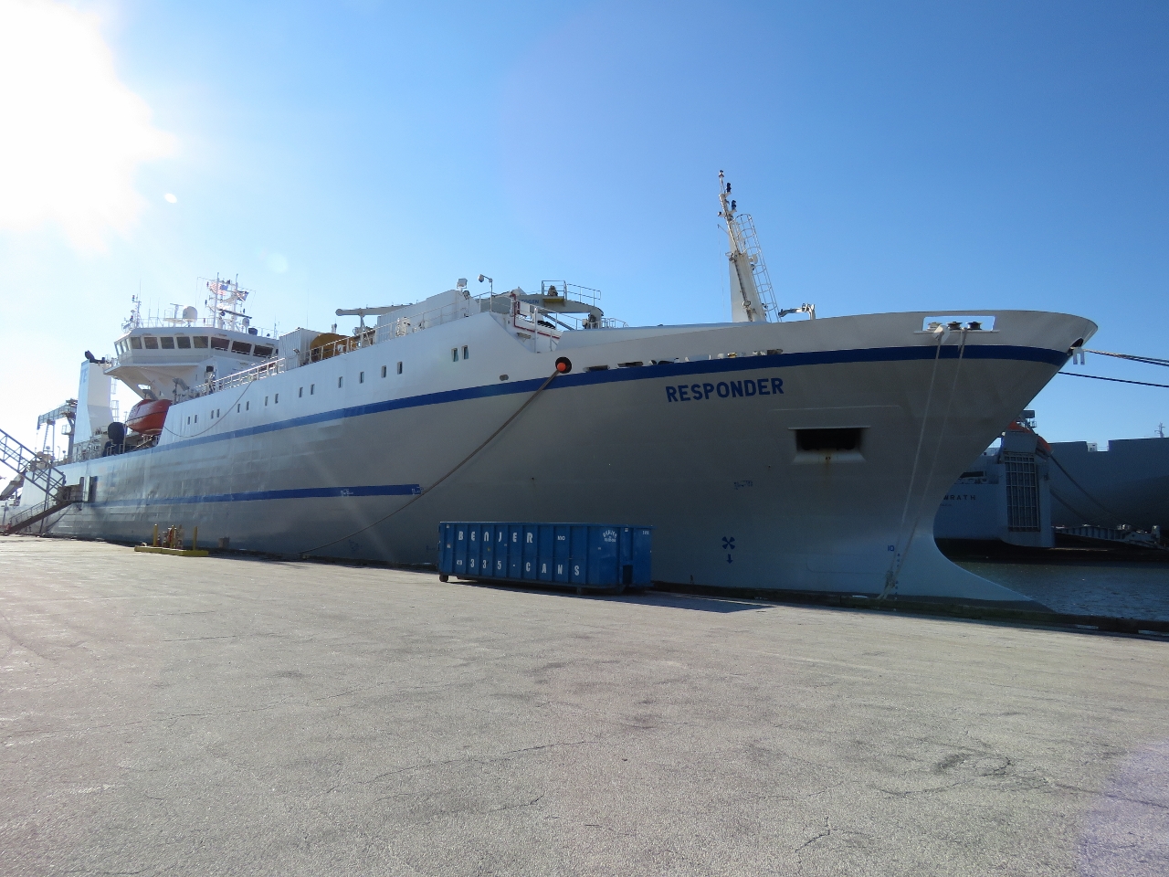
Laying fiber optic cables with repeaters along the ocean floor raises super-interesting technical challenges. I recently visited the CS Responder, a trans-ocean cable-laying ship operated by TE Connectivity.
TE Connectivity is $13.3B global technology company that specializes in communication cable, connectors, sensors, and electronic components. Their subsidiary TE SubCom manufactures, lays and maintains undersea cable. TE SubCom has a base in Baltimore and invited us to tour the facility and one of their cable-laying ships. The visit included an overview of their cable-laying business and solutions, demonstrations on how undersea cables are made, and best of all, a tour of the CS Responder.
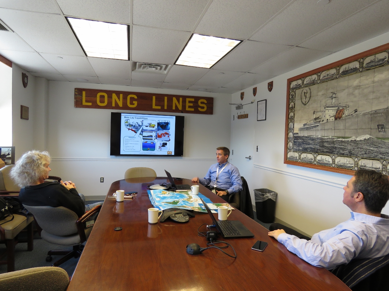
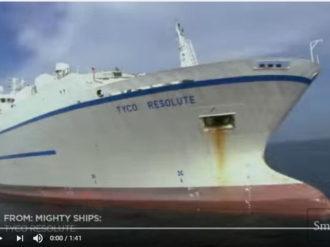
In the first picture below our guide on the tour, Jim Herron, is on the left and our host David Robles on the right. Jim started the day with an overview of the TE SubCom cable-laying business and the many challenges faced in the process, ranging from permitting to adverse weather to the job of actually laying the cable itself. A sister ship to the CS Responder, the Tyco Resolute (now CS Resolute) was featured on Discovery Channel Canada’s Mighty Ships documentary series. This episode, although somewhat dramatized, shows many of the challenges that cable-layers face and how they are managed. The Smithsonian Channel airs the series in the US. A trailer is on the Smithsonian Channel web site and the full episode is available on Amazon Video.
 |
 |
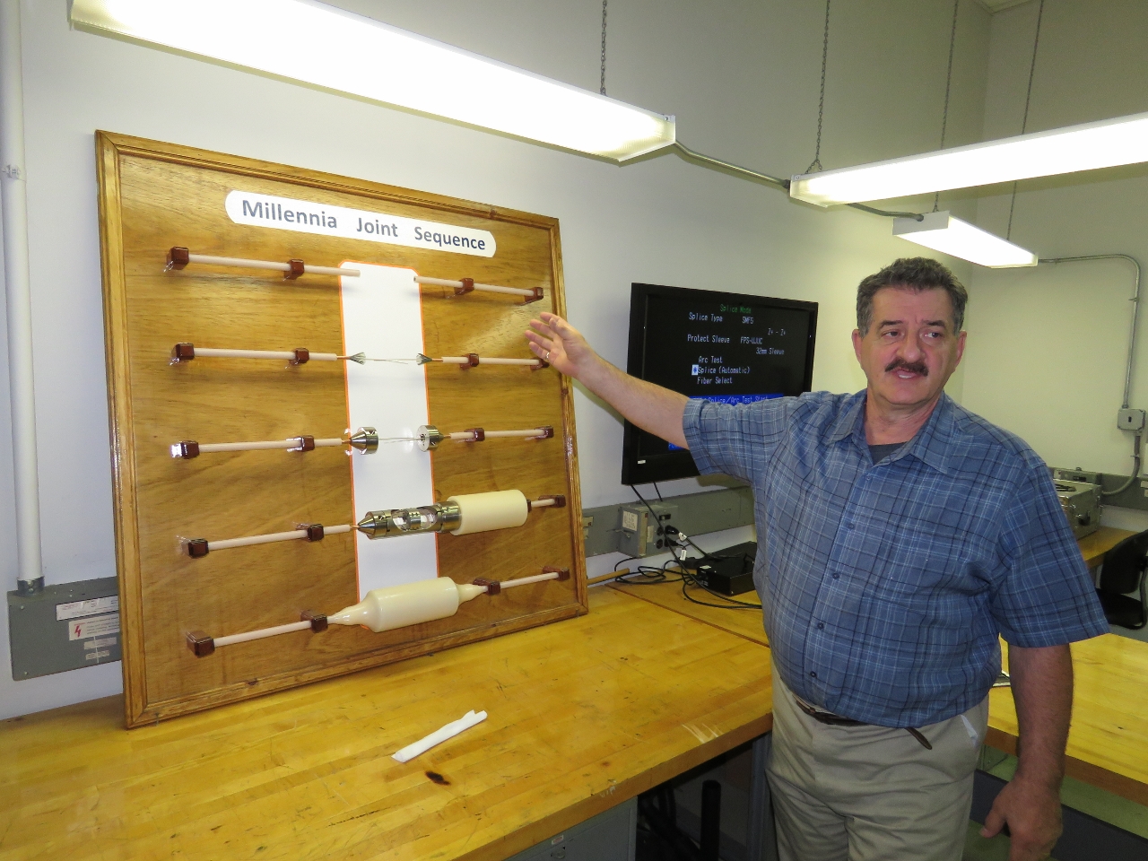
Our first stop was the shore-based splicing training school. Brian Isenstadt showed us how splicers are trained to reliably connect tiny fiber optic links where the links are low-loss and sealed from water well enough to last 20+ years. The second photo below shows the stainless steel cartridge that maintains the mechanical strength of the cable and provides space for the up to eight individually-spliced tiny fiber-optic pairs.
 |
 |
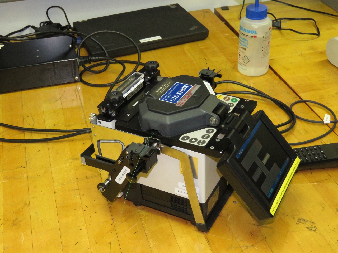
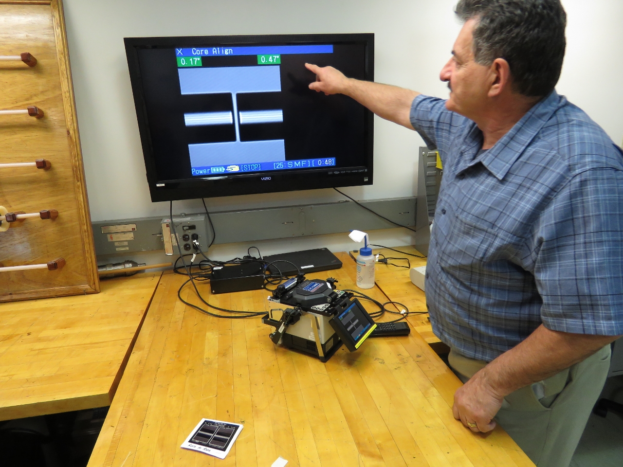
The first picture below shows the instrument that first aligns the optics and then fuses them together into a single unbroken fiber optic path. The screen in the second picture shows the two fiber ends being brought together into alignment to ensure a low signal-loss connection.
 |
 |
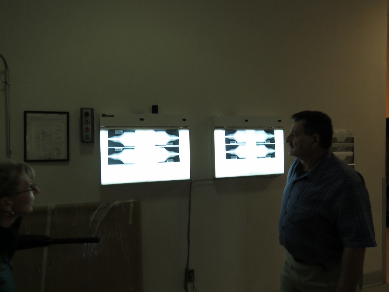
The stainless steel splice cartridge is next permanently encased in a waterproof thermally-injected sealant. In the second picture below, the sealing material is inspected carefully for impurities, bubbles, or other flaws using X-ray.
 |
 |
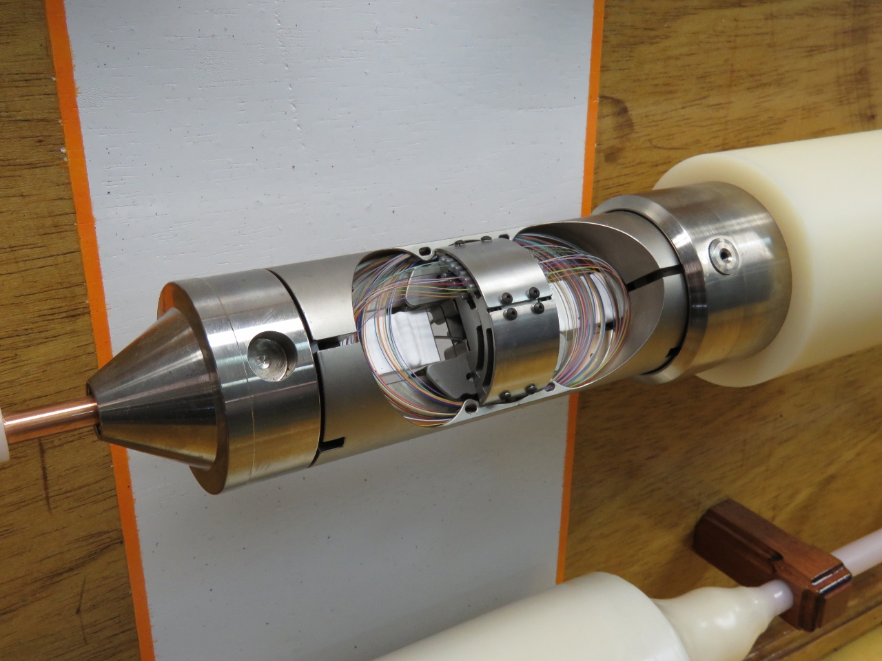
Repeaters are one of the biggest challenges to undersea cable longevity. High quality optical signals will only propagate for 60 to 80 km within high signal-to-noise standards. So, to cross an entire ocean, repeaters have to be used to boost the signal strength. These repeaters have to be able to operate reliably for 20+ years at depths beyond 3 miles. And they have to be strong enough to make it highly unlikely the cable will be torn apart at the repeater by weather, fishing activity, or other disturbances.
These repeaters are electrically powered with direct current (DC) and the power distribution system used is super interesting. Each repeater is in series like an old-fashioned Christmas tree light string. This allows only a single conductor to be used to power all repeaters, greatly decreasing the cost of the cable. The downside of single-conductor DC powering is that shore side Power Feed Equipment (PFE) has to provide sufficient voltage to drive the potentially multi-thousand mile cable and all the cable repeaters along the ocean floor. To achieve the needed levels of redundancy, the PFE on one cable end supplies positive voltage and the PFE on the other ends supplies a roughly equal negative voltage. The combined difference of potential or voltage could be as high as 10,000 volts, although each repeater only sees a tiny portion of that difference of potential since they are all wired in series.
The two most common undersea cable failure modes are 1) PFE failure and 2) undersea cable power shunts to ground. Both failures have similar recovery mechanisms. If a PFE fails, the PFE on the other end doubles its voltage level to maintain the same difference of potential at each repeater allowing the cable to continue to operate without interruption until the PFE can be repaired. In the second fault mode, there is an insulation failure in the cable perhaps caused by fishing activity or weather action. This will allow the voltage at the insulator failure to drop to the ground plane neutral of the sea water. The recovery mode for power shunts to ground is for each PFE to adjust the inserted voltage such that the PFE on each end powers all repeaters between that PFE and the shunt-to-ground fault. In this operating mode, the cable will again continue to operate correctly even with the ground fault somewhere along the cable length. And, as long as the shunt fault is repaired before there is a second fault of either type, the cable will continue to operate without negative customer impact.
Below are cutaway repeaters showing their construction.
 |
 |
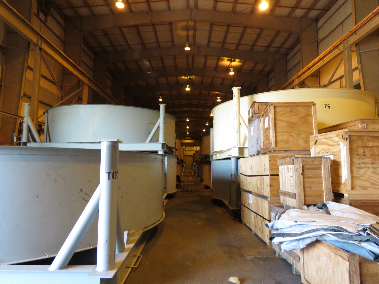
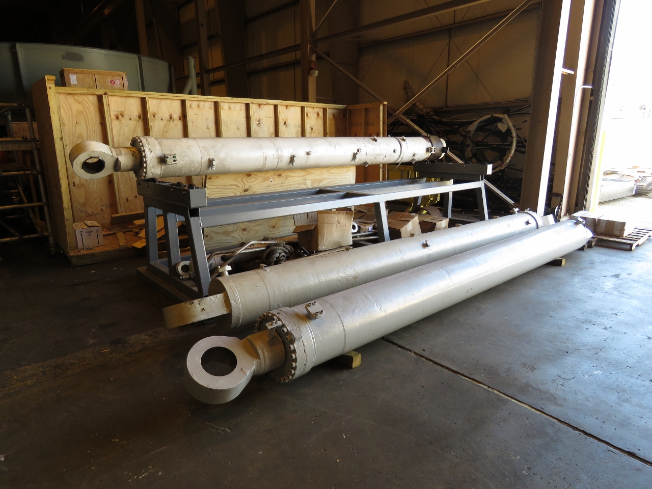
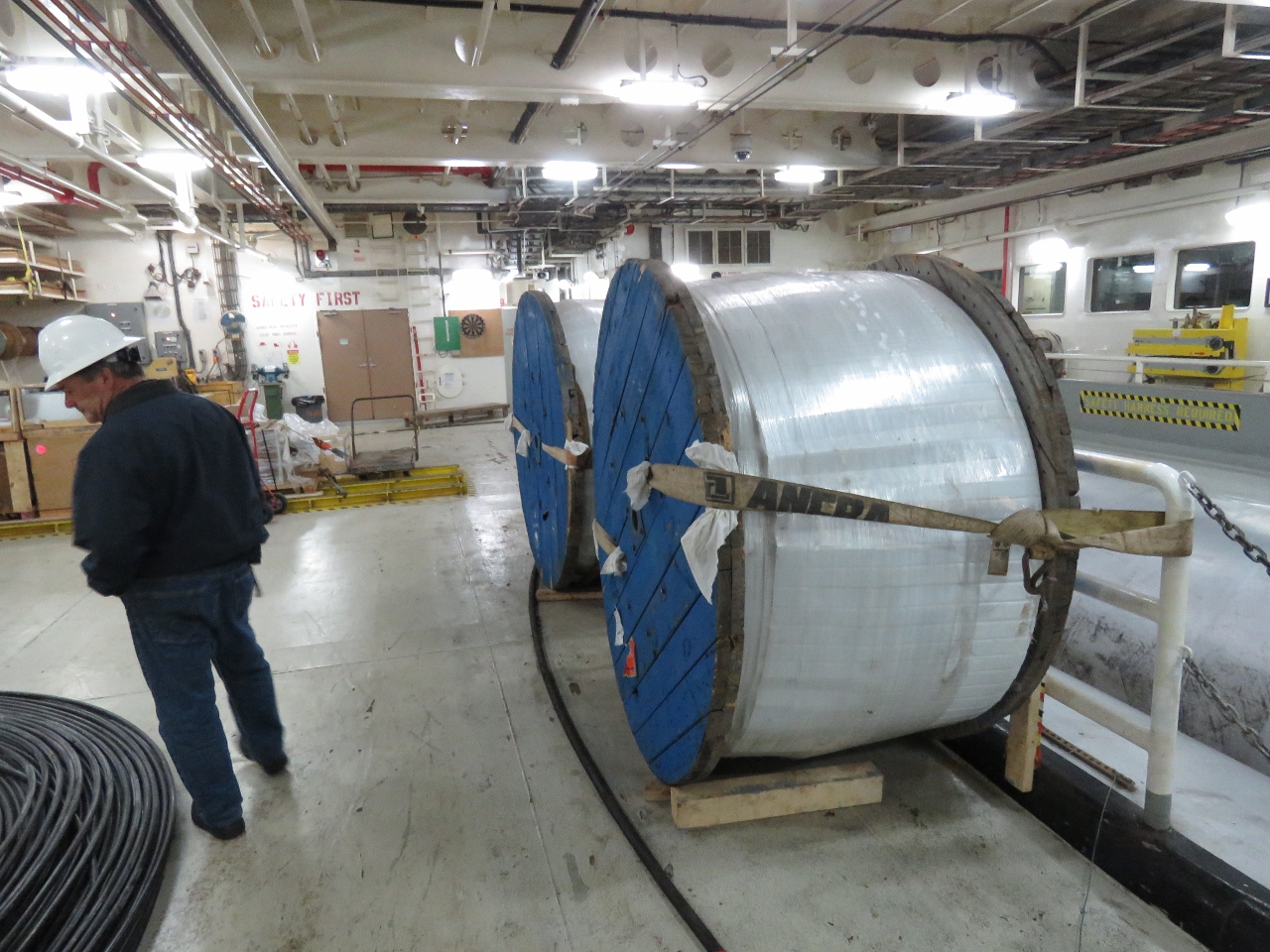
We toured the shore-side storage facilities on our way to the Responder. Left below are customer-owned fiber-optic cables in large metal cylinders used for storage and transport. On the right are large hydraulic cylinders needed at sea for the cable-laying process.
 |
 |
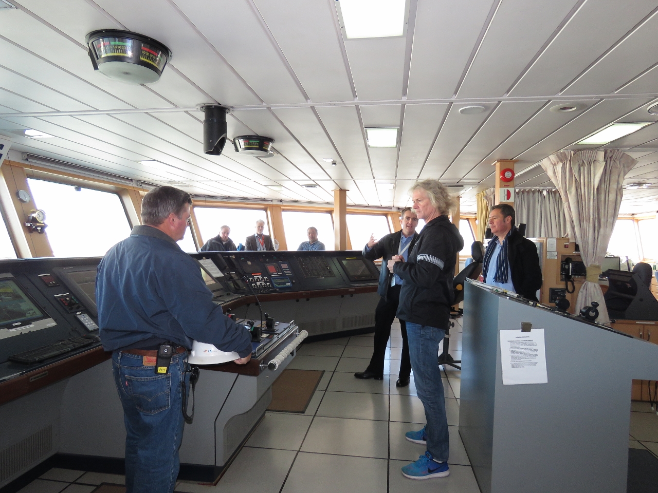
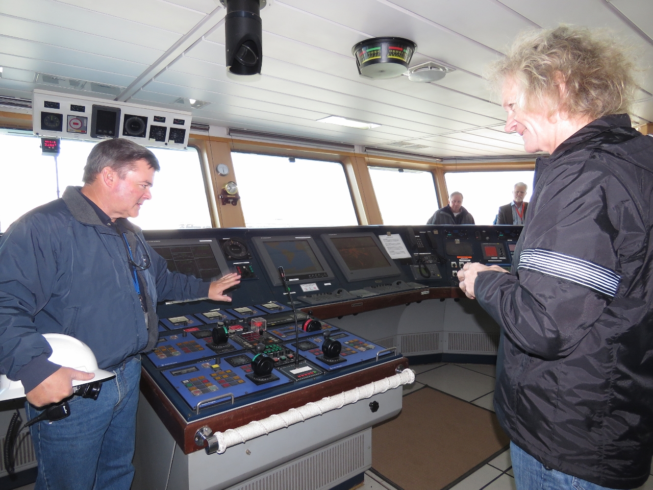
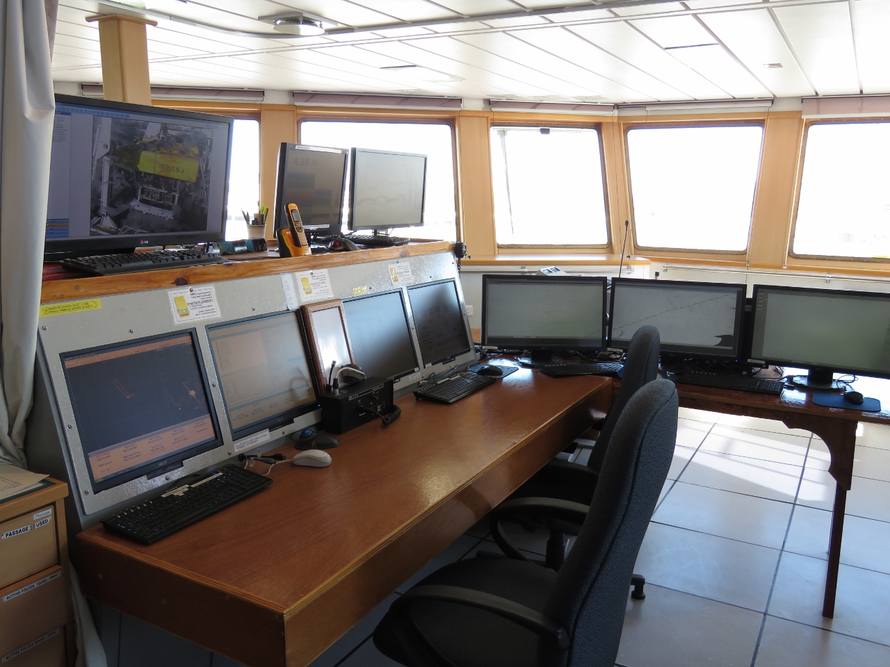
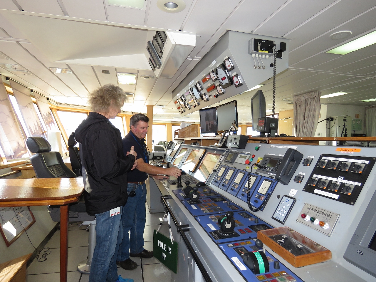
The Responder’s two captains (two shifts), Daniel Kenealy and Chris Gabrielson, took us through the ship starting with the bridge. Below Capt. Kenealy is explaining each bridge station and their use. Specialized stations for different ship operating modes are located throughout the bridge. When steaming underway, the central bridge stations are used to operate the ship. During docking the ship can be maneuvered by the captain directly via the wing control station at the far left and right side of the bridge. Kenealy explained he prefers instead to get to a location with a better view and gently ease up to the dock via radio commands given to a helmsman.
From the aft end of the bridge, an excellent view can be had of the working deck over which cable is laid, the ROV (remote operated vehicle) is launched and recovered, and the cable-burying sea plow is deployed and recovered.
 |
 |
This ship is DP2-capable, meaning it can maintain its position with high degrees of precision in rough seas and with redundancy. The dynamic positioning system’s computer will apply thruster or propeller force to hold the boat in an exact GPS-sensed location. This technology is commonly used in the oil exploration business where it is often necessary to keep a boat in an exact position in bad weather and rough seas where any deviation can do substantial damage or even put workers at risk. Because this is a life-critical system and potentially with high-value equipment at risk, it must operate without exception through computer faults or equipment failures.
The DP2 system on the Responder primarily is used to hold position against wind and current in order to place the cable precisely as the ship slowly inches forward laying cable at speeds that can sometimes sink below 1 kt and seldom are far above 3 kts. The dynamic positioning system also is used for remote-operated-vehicle submarine operations and when doing some non-cable related contracts where the ship is near oil rigs or related-equipment.
 |
 |
A row of cable repeaters is in the first picture below. The subsequent picture is new rope used for raising and lowering cable.
 |
 |
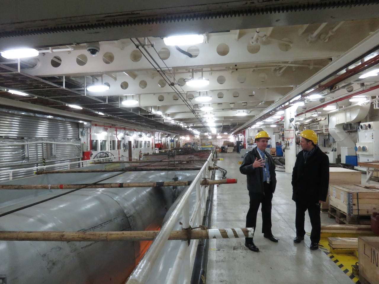
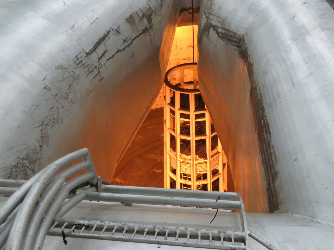
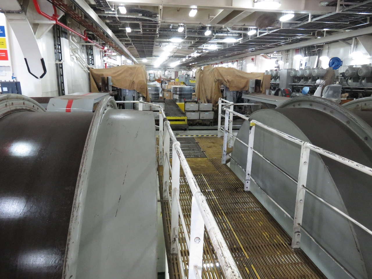
The first picture below is looking across the three massive cable storage areas in the Responder. If you look carefully, you can see a cable spooling out on the left from the rear storage area and heading out across the two forward in-ship storage areas. The crew was in the process of delivering some cable moved from their Bermuda storage facility to the Baltimore depot. The second picture is looking down into the rearmost of the three cable storage areas on the boat. The cable being offloaded is visible at the top of the photo, feeding up from the bottom of the storage area where it is neatly spiraled (click any photo for a larger view).
 |
 |
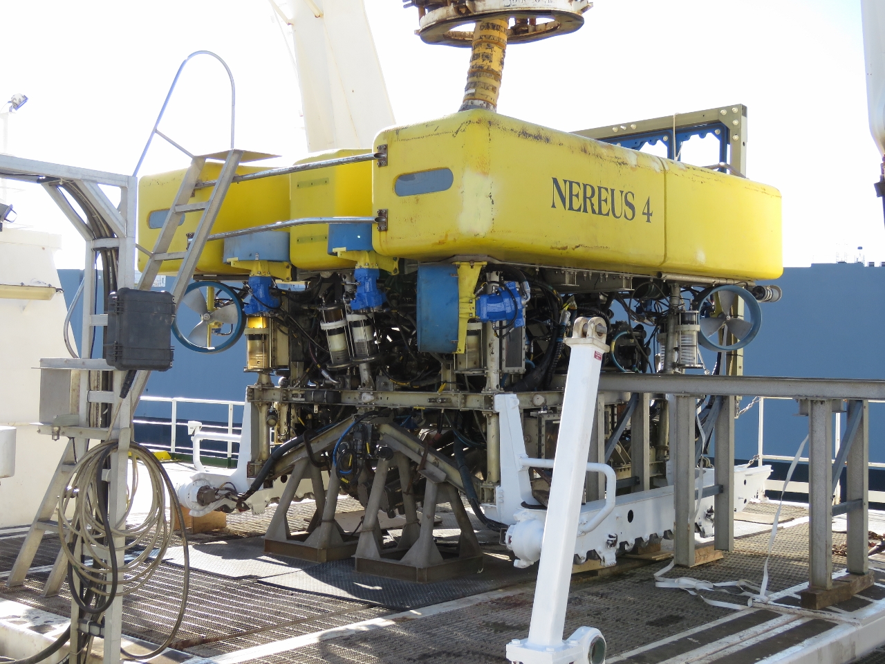
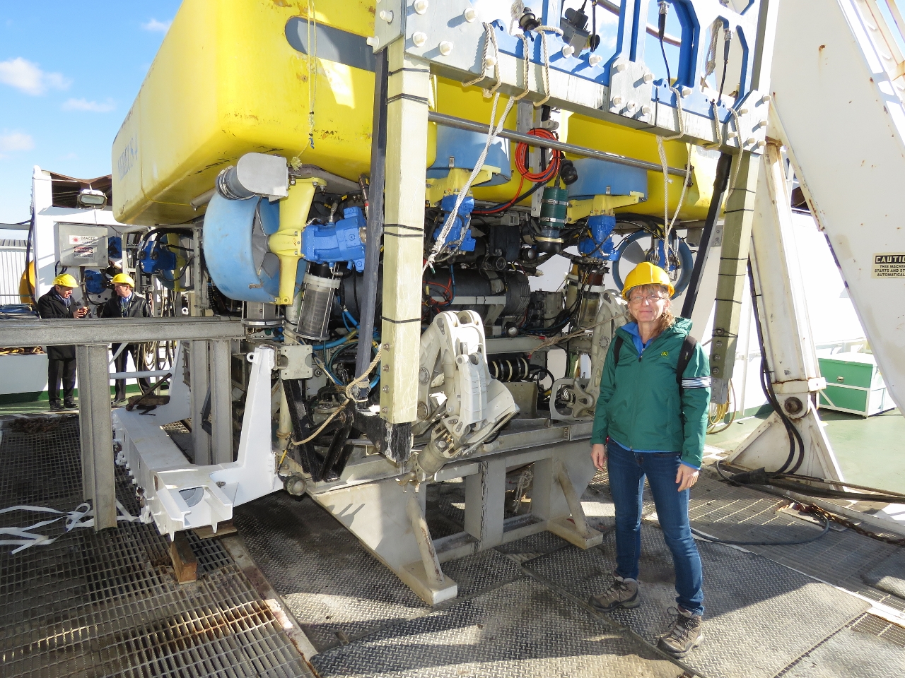
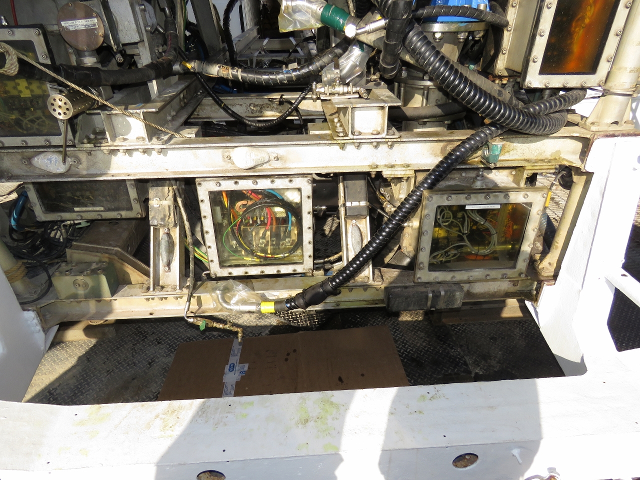
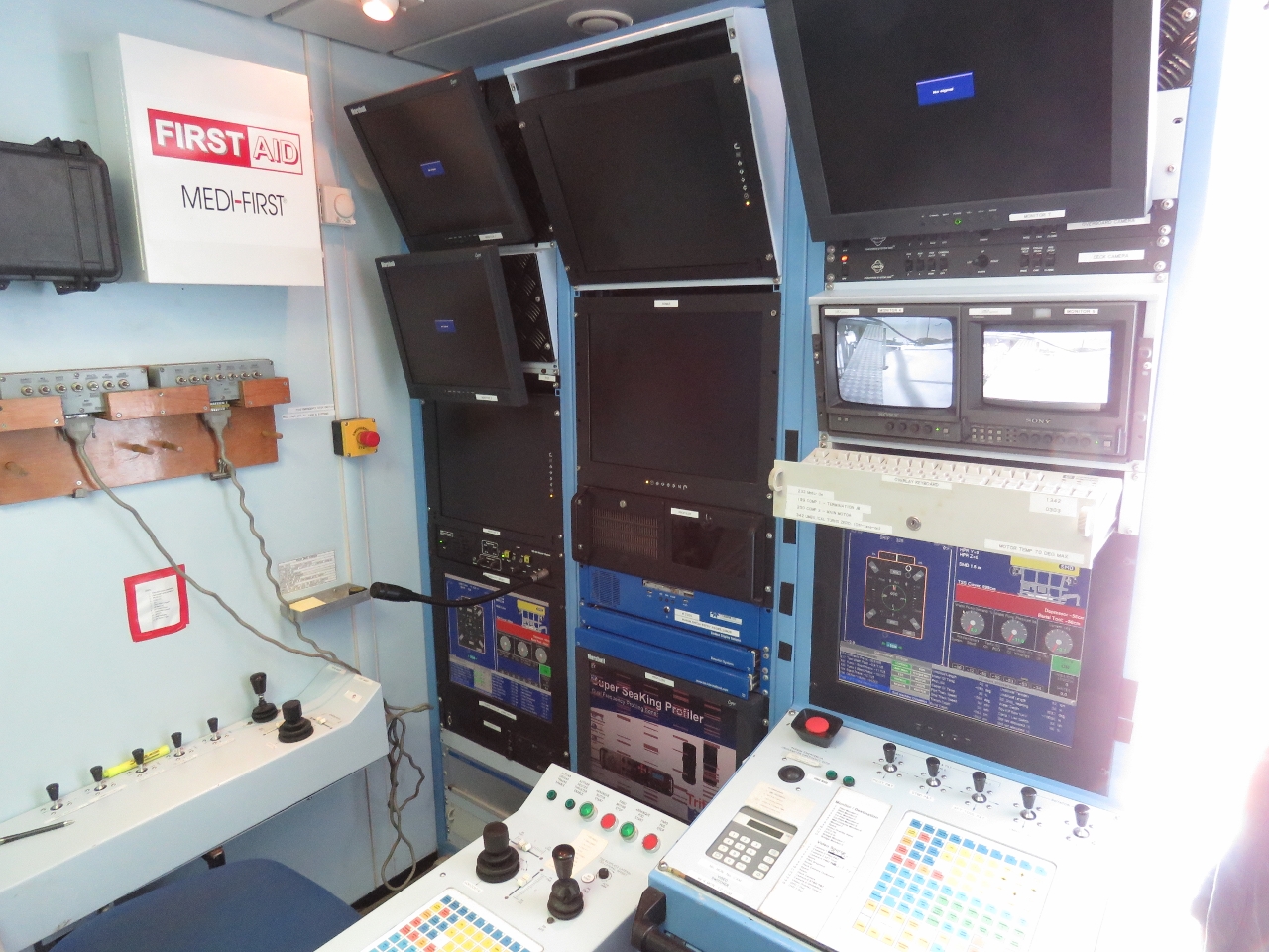
Below are pictures of the remote operated vehicle (ROV) used on the Responder and the control center where operators pilot the ROV. This vehicle is used to inspect cable lay positions, move cables to safer locations, and for non-cable related contracts. Sealing the electronics used in the ROV against the seawater outside is a real challenge. This system runs the electronics in an oil bath sealed against seawater intrusion.
 |
 |
 |
 |
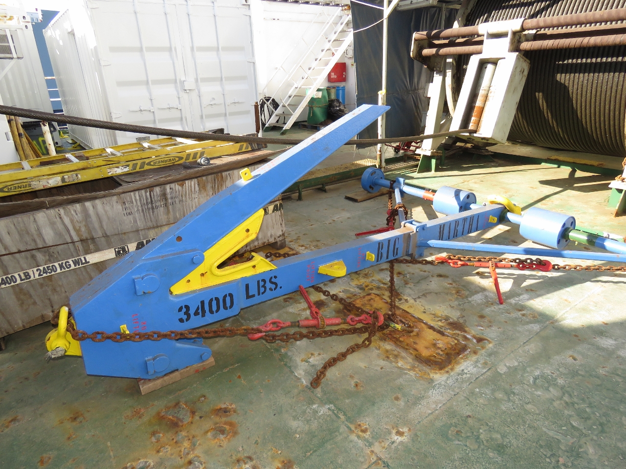
When cables need to be branched or any repair needing splicing, the cable may need to be cut, captured and lifted onto deck for service using a cutting grapnel.
 |
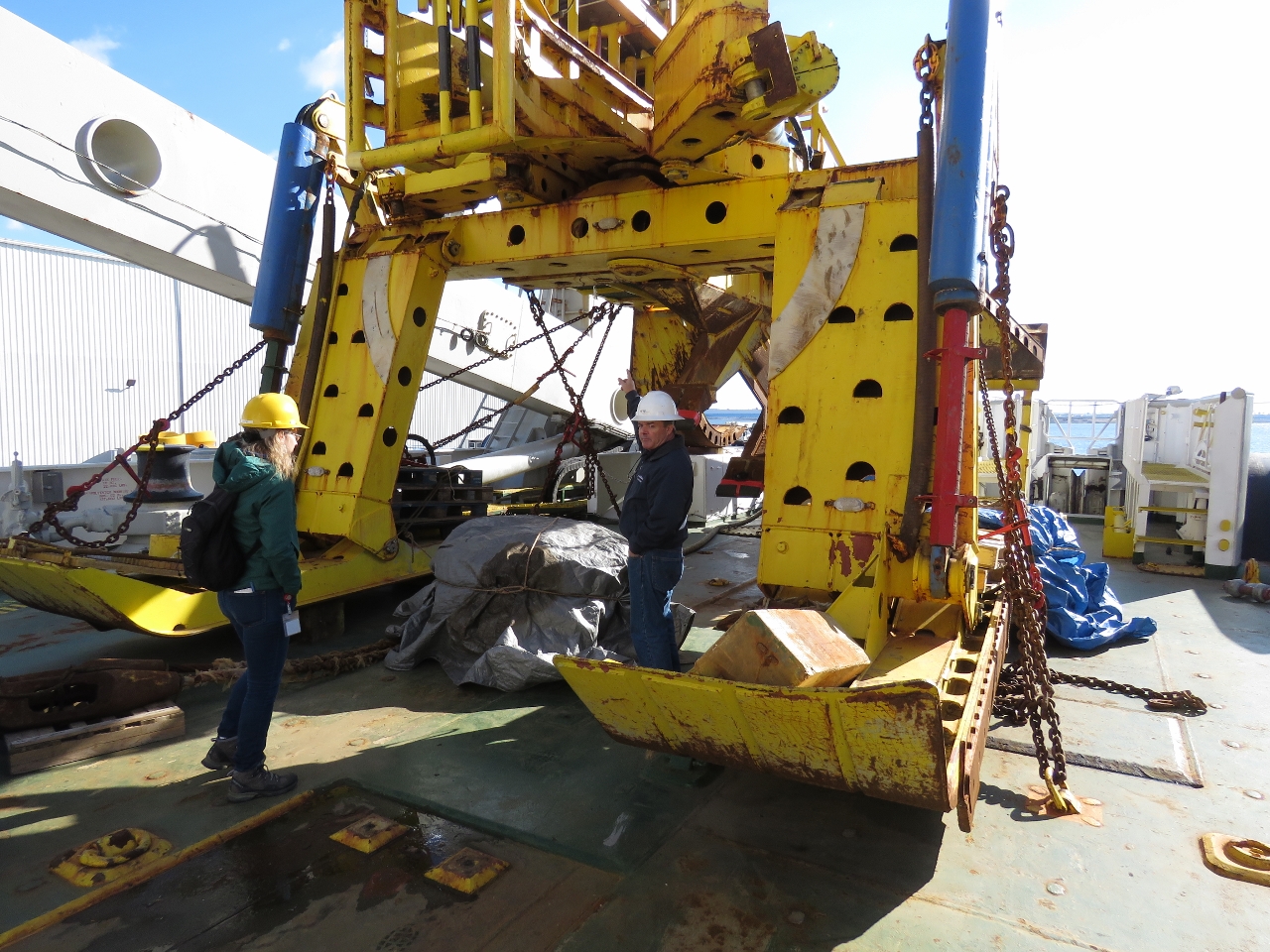
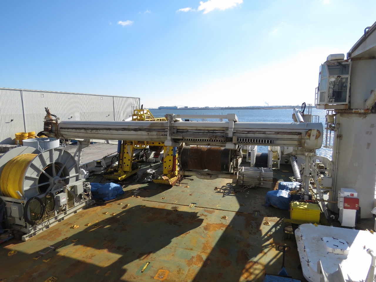
The following two pictures are of the massive EB Sea Stallion sea plow that is dragged behind the ship when burying cable. This beast can bury cable up to 3 meters by dragging a plow section that cuts through the sea bottom as it pulls forward and the cable is fed in through the blade to the bottom of the trench. The sea plow needs to be precisely controlled and dragged at just the right speed to allow complete burial depending upon sea bottom topography. Considerable skill is required to maintain just the right tension on the plow and the communications cable feeding into it.
 |
 |
The control room for the EB Sea Stallion sea plow is in a shipping container mounted on deck. The plow is visible towards the stern of the ship on the left of the second picture below.
 |
 |
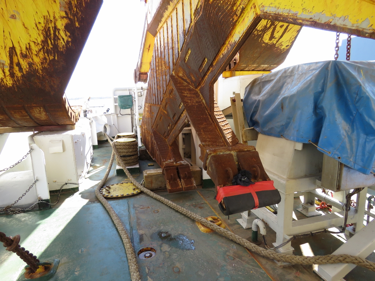
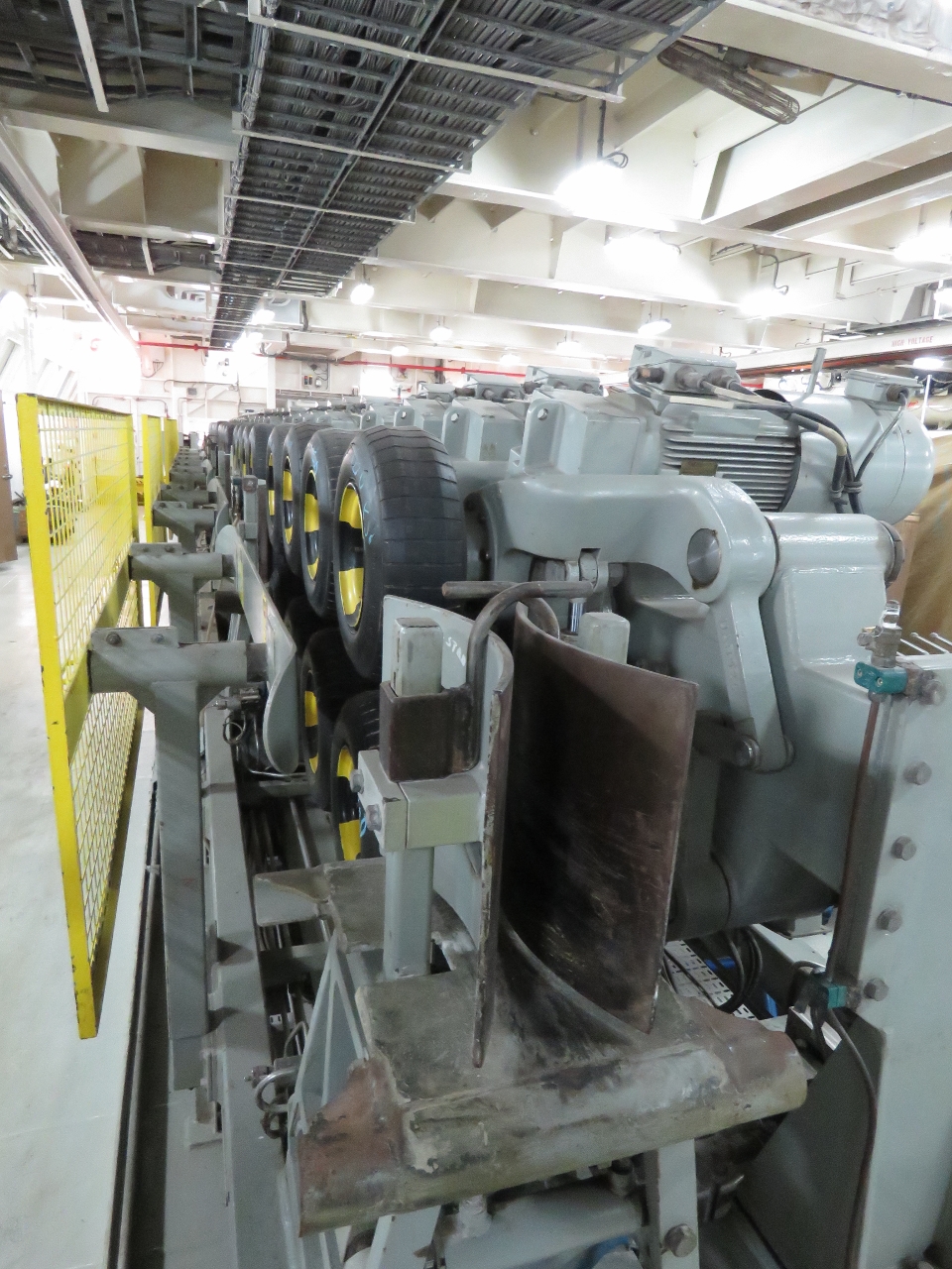
The next three photos show the cable management gear towards the stern of the ship, aft of the three cable storage areas. The cable itself is fed out through a row of rubber tires that grab the cable through friction. Each of these rubber tires is powered by a large electric motor that allows the cable to feed out smoothly at exactly the speed needed without putting the cable under excess load, creating heat through friction, or putting unnecessary mechanical forces that could damage the cable.
 |
 |
 |
Before getting into the details, most industries look far simpler than they really are. In this case, how complex can it be to run a fiber optic cable across a body of water? But the deeper you dig, the more the challenges mount.
When running undersea cables, the ends are almost always in different countries, each having their own permitting process and regulations. Cables need to be as light and inexpensive as possible but, when not protected by extreme depths, they need to armored against damage from anchoring, trawling, and severe weather events. When near shore, cables need to be buried in the sea bottom as deep as 3m to further minimize the damage risk.
Signal integrity can only be maintained by repeaters every 60 to 80 km. These repeaters need to be electrically powered and they need to continue to operate through both power failures and cable insulator faults. Repeaters need to operate reliably for 20+ years even when operating more than 3 miles below the sea surface. Cables need to be spliced together without signal loss while maintaining both mechanical strength and resistance to water intrusion.
TE SubCom controls all the technology from the cable design and manufacture, the repeater design, all the way through to the cable laying and service ships, allowing TE Connectivity to deliver multi-decade solutions both efficiently and economically.
 |
Thanks to the captains and crew of the CS Responder for their hospitality and patience with all of our questions and Mike Rieger, Dave Robles, and Jim Herron of the shore-side team at TE SubCom.
I realise this is an old article, but as a small update there was a fire onboard this vessel and it sank while working on a project for Korea Telecom. All crew were safely evacuated.
https://subtelforum.com/cs-responder-fire-all-60-personnel-evacuated/
That was a well equipped cable layer. Sad to see it was lost but thanks for letting us know.
Good news. It appears the boat that sunk is a different cable layer with the same name. Which seems pretty amazing but the CS Responder is still in service and doing well: https://www.marinetraffic.com/en/ais/details/ships/shipid:711443/mmsi:538001582/imo:9236509/vessel:RESPONDER.
The ship that sank was the old “Maersk Responder” which was purchased by Korea Telecom and renamed (partially renamed) KTS Responder.
Thanks for the details confirming that the CS Responder is still in operation.
This is an Amazing video much in the likes Amazon Web Services. I have never see Deep Ocean Cables being layed. We only see splicing in a micro level at the fibre optics that we deal with. I used to work designing the Wafer Heads on Magnetic Disks , but now I realise the complexity it takes to have internet speeds over the ocean floor . Just preparing from my AWS Interview on coming Wed
I hope the interview goes really well. It’s a really fun time to be at AWS.
I just saw The Responder on Sydney Harbour and had to look it up. I found your article which is a fabulous insight into cable laying. It is such a complex process for a simple description. A great read and the photos were eye-opening.
Thanks Di. By coincidence, yesterday I saw a news article saying that work had started on the Hawaki cable and laying has begun on the Oregon end and is just about to start on the Sydney end with Responder about to get underway. It’s an impressive operation.
10-23-2017
Do the ships: CS Responder/Resolute–Trans–Oceanic Cable Layers currently have any territorial limitations ? if not do you have any idea
how far north to other island countries may have been reached with cable ?
There are many restrictions on all cable layers when they enter a countries territorial waters. In fact, that’s one of the larger challenges of cable laying is all the clearances, approvals, and agreements needed shore side. This cable connects Australia, New Zealand, and Oregon on the US west coast but also connects the pacific islands of Hawaii, Pago-Pago, Neiafu, Suva, and Noumea.
Fascinating article!
(one niggle: sever -> severe toward the end)
I updated the main article. Thanks for the correction.
Readers may be interested in this FAQ sheet from Telegeography, which contains an interactive map of the world’s most significant submarine cables.
http://blog.telegeography.com/frequently-asked-questions-about-undersea-submarine-cables
An Oldie but Goodie, The mother of all fiber-optic cable laying accounts:
Mother Earth Mother Board
https://www.wired.com/1996/12/ffglass/
I agree it’s a good article. Wired did a great job of that one.
Another great book related to the subject is “Tubes: A Journey to the Center of the Internet” by Andrew Blum. Went on a ‘walking tour of the internet’ in NYC with him a few years ago. Neat stuff.
Thanks for the pointer to Tubes: A Journey to the Center of the Internet” Andrew.
“A Thread Across the Ocean” is a great read on the first trans-Atlantic cable (in 1866!). Highly recommended. Thanks for the post.
My thought exacty! I have a copy of “A Thread Across The Ocean” on Dirona and plan to read it very soon. Thanks!
I am glad that the oceans are not opaque and awestruck by the photos. “This system runs the electronics in an oil bath sealed against seawater intrusion.” left me speechless. Thanks for sharing this.
Thanks, its very instructive.
I’m curious about the Optical-Electronic-Optical repeaters. Were Erbium-Doped Fiber Amplifiers (EDFAs) considered, or are they immature and unsuitable for undersea deployment?
EDFAs are in use in undersea cables and I believe that all modern undersea cables are using EDFA repeaters. Here’s an old article from 1997 talking about the bandwidth improvements driven by the move to EDFA: http://www.laserfocusworld.com/articles/print/volume-33/issue-8/world-news/optical-amplifiers-speed-data-flow-undersea.html
That 1997 article references 5Gbps speed wheras current fiber pairs are running 100 waves of 100Gbps.That’s 10TB per fiber pair. TE Subcom is currently supporting up to 8 fiber pairs per cable so 80Tbps bidirectional is supported today in a single cable.
Hello,
My name is Vito Ferrara, and I am an Electronics Supervisor for TE Connectivity SubCom.
This is such an awesome report!
I’m constantly getting questions from family and friends about what we do and how we do it. I hope you don’t mind me posting the link to my Facebook or the extra traffic to your site. Thanks for visiting us. Come back soon.
Thanks for the feedback on the blog Vito and thanks to you and the rest of the TE Connectivity team for spendig time with us and showing us the details behind what you do.