When I come across interesting innovations or designs notably different from the norm, I love to dig in and learn the details. More often than not I post them here. Earlier this week, Google posted a number of pictures taken from their datacenters (Google Data Center Tech). The pictures are beautiful and of interest to just about anyone, somewhat more interesting to those working in technology, and worthy of detailed study for those working in datacenter design. My general rule with Google has always been that anything they show publically is always at least one generation old and typically more. Nonetheless, the Google team does good work so the older designs are still worth understanding so I always have a look.
Some examples of older but interesting Google data center technology:
· Efficient Data Center Summit
· Rough Notes: Data Center Efficiency Summit
· Rough notes: Data Center Efficiency Summit (posting #3)
· 2011 European Data Center Summit
The set of pictures posted last week (Google Data Center Tech) is a bit unusual in that they are showing current pictures of current facilities running their latest work. What was published was only pictures without explanatory detail but, as the old cliché says, a picture is worth a thousand words. I found the mechanical design to be most notable so I’ll dig into that area a bit but let’s start with showing a conventional datacenter mechanical design as a foil against which to compare the Google approach.
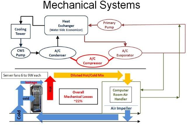
The conventional design has numerous issues the most obvious being that any design that is 40 years old and probably could use some innovation. Notable problems with the conventional design: 1) no hot aisle/cold aisle containment so there is air leakage and mixing of hot and cold air, 2) air is moved long distances between the Computer Room Air Handers (CRAHs) and the servers and air is an expensive fluid to move, and 3) it’s a closed system and hot air is recirculated after cooling rather than released outside with fresh air brought in and cooled if needed.
An example of an excellent design that does a modern job of addressing most of these failings is the Facebook Prineville Oregon facility:
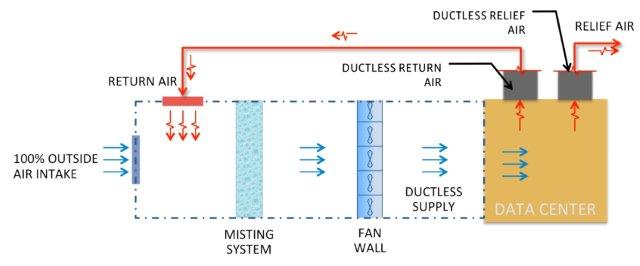
I’m a big fan of the Facebook facility. In this design they eliminate the chilled water system entirely, have no chillers (expensive to buy and power), have full hot aisle isolation, use outside air with evaporative cooling, and treat the entire building as a giant, high-efficiency air duct. More detail on the Facebook design at: Open Compute Mechanical System Design.
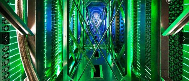
Let’s have a look at the Google Concil Bluffs Iowa Facility:
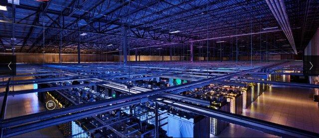
You can see that have chosen a very large, single room approach rather than sub-dividing up into pods. As with any good, modern facility they have hot aisle containment which just about completely eliminates leakage of air around the servers or over the racks. All chilled air passes through the servers and none of the hot air leaks back prior to passing through the heat exchanger. Air containment is a very important efficiency gain and the single largest gain after air-side economization. Air-side economization is the use of outside air rather than taking hot server exhaust and cooling it to the desired inlet temperature (see the diagram above showing the Facebook use of full building ducting with air-side economization).
From the Council Bluffs picture, we see Google has taken a completely different approach. Rather than completely eliminate the chilled water system and use the entire building as an air duct, they have instead kept the piped water cooling system and instead focused on making it as efficient as possible and exploiting some of the advantages of water based systems. This shot from the Google Hamina Finland facility shows the multi-coil heat exchanger at the top of the hot aisle containment system.
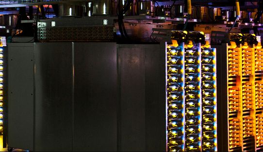
From inside the hot aisle, this shot picture from the Mayes County data center, we can see the water is brought up from below the floor in the hot aisle using steel braided flexible chilled water hoses. These pipes bring cool water up to the top-of-hot-aisle heat exchangers that cool the server exhaust air before it is released above the racks of servers.
One of the key advantages of water cooling is that water is a cheaper to move fluid than air for a given thermal capacity. In the Google, design they exploit fact by bringing water all the way to the rack. This isn’t an industry first but it is nicely executed in the Google design. IBM iDataPlex brought water directly to the back of the rack and many high power density HPC systems have done this as well.
I don’t see the value of the short stacks above the heat exchanges. I would think that any gain in air acceleration through the smoke stack effect would be dwarfed by the loses of having the passive air stacks as restrictions over the heat exchangers.
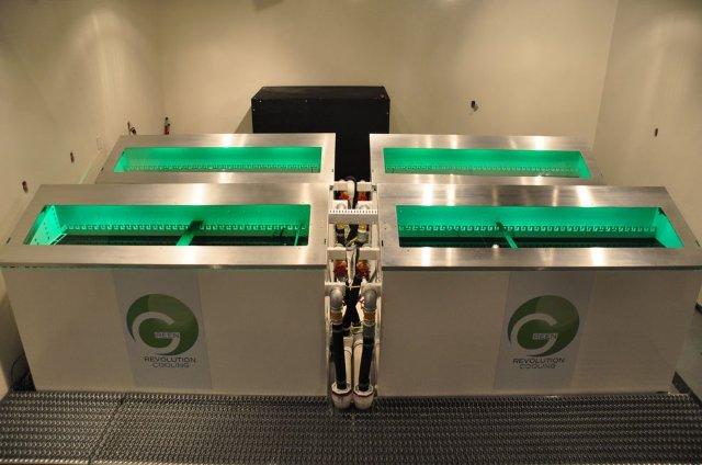
Bringing water directly to the rack is efficient but I still somewhat prefer air-side economization systems. Any system that can reject hot air outside and bring in outside air for cooling (if needed) for delivery to the servers is tough to beat (see Diagram at the top for an example approach). I still prefer the outside air model, however, as server density climbs we will eventually get to power densities sufficiently high that water is needed either very near the server as Google has done or direct water cooling as used by IBM Mainframes in the 80s (thermal conduction module). One very nice contemporary direct water cooling system is the work by Green Revolution Cooling where they completely immerse otherwise unmodified servers in a bath of chilled oil.
Hat’s off to Google for publishing a very informative set of data center pictures. The pictures are well done and the engineering is very nice. Good work!
· Here’s a very cool Google Street view based tour of the Google Lenoir NC Datacenter.
· The detailed pictures released last week: Google Data Center Photo Album
–jrh
James Hamilton
e: jrh@mvdirona.com
w: http://www.mvdirona.com
b: http://blog.mvdirona.com / http://perspectives.mvdirona.com
The PUE advantage is real but just happenstance and almost certainly not a factor in why they chose that design.
How long can the servers keep running without room level air handlers in conventional designs? Assuming the server fans are still working, surprising long. Most data centers run with considerable engineering headroom (running much cooler than needed)and have the entire room as a plenum. I would guess 20 to 25 min before the servers started to do emergency thermal shutdowns.
I totally agree with you that "less is more" when it comes to data center design. Less equipment is less capital cost, less maintenance, and fewer failure modes.
Thanks for confirming. I couldn’t tell for sure if that was the case from google’s release.
I’ve come across the concept of fan-less servers before, but never saw any realistic possibility in it other than for the 1%’ers (i.e. google and you guys) who might build out their own spec equipment to integrate into a holistic DC design (thinking FB open compute). For the rest of us, equipment comes as it is – we must design DC’s around that fact in the most efficient and reliable way possible. In an aside, I wonder how long it would take a fan-less server core to burn out without room fed CFM?
Your comments on advantages/disadvantages are spot on. Again, from my first comment, the scale-ability of this design is beautiful. With Google’s design you don’t have to design/ model supply CFM, purchase, install, operate, and maintain new air handlers as room load scales up. You simply take on more chiller load (or scale up chiller capacity modularly as you scale up the floor level heat exchangers). Of course, room level CFM is almost never built out or scaled up at just need (N). Most often, it is built and scaled at N + 20/25% for redundancy – so you can extend the savings from above by that same multiplier. Likewise, the power infrastructure and subsequent redundant power infrastructure (gen set distro) to support floor level CFM/air handlers is also forgone. Everything you put into a data center adds complexity and a threshold/capacity to manage. Taking something out, as google has done, is truly eye opening to me.
Lastly – doctor PUE!!! who would do such a thing =)
Yes, the design is to not use Room level air movers (CRACS, CRAHS, or separate fans) and instead just use the server fans. You were asking if this was a unique design. It might be. Proposals to eliminate a set of fans are fairly common but most of these design proposals are eliminating the server fans and depending only on very large room-scale air movers. The advantage of these designs is large fans are more efficient than small ones. The disadvantage of the approach is we would need to move enough air for the the worst server where worst is: requires most air flow. The Google design has each server moving the air it needs which minimizes the air movement (good) and increases the deltaT at the cooling coils (good).
Another nice side effect of the design is that, when computing PUE, the server fans are counted as critical load so this approach can make the PUE look very good. Not the goal I’m sure but an interesting side effect.
–jrh
I have not looked through the entire photo gallery yet, but what immediately strikes me is the lack of dedicated HVAC fan HP. It’s a given that moving the heat transport to water (higher efficacy) as close to the rack as possible is the low hanging fruit, but I don’t see any fan HP moving the air at all. Again, maybe i’m missing something, but it appears that google has cut external fan power (large AHU’s ect.) in preference for internal fan power(IT equipment inboard fans). In that sense, all static air pressure is maintained by the output of the IT equipment inboard fans. Thinking out loud – the output of the IT equipment inboard fans pressurizes the hot aisles – facilitating air movement across the water cooled heat exchanger. The now cooled air then naturally stratifies through the room to supply "cold aisle" set-point. From an HVAC system scaling perspective, this a magnificent concept. As IT equipment scales up in utilization (or new deployments) the supply air moving through the system is automatically augmented by the IT equipment itself (via inboard fan quantity or throttling). There are obviously some mechanical questions to ask with this/my simplistic "input CFM = output CFM" theory; pressure drop across the coil, coil efficiency at low CFM, chiller performance at what would appear to be low delta T, and so forth. However, I’m sure those questions have been answered by google if we are seeing this design in pub. Another interesting part of this design to me is the dollar cost perspective – IT inboard fans are sunk CAPEX and semi-sunk OPEX expenses. Google appears to have decided to maximize these sunk costs to their fullest – in lieu of sinking more cost to supply external fan HP (air).
To the author – have you seen this or similar designs before? Again, I may be missing something with the quick look but this concept is blowing my mind. thanks for the great content.